Die Casting Tolerance: How to Specify DCTG Grades
Most drawings that arrive at our shop carry one small line: General tolerance ISO 8062-3 DCTG7.
That single line decides how hard the part is to make, whether it needs CNC afterwards, and how much it costs. And in a large share of the RFQs we receive, it is either missing — or it says DCTG7 while three critical fits on the same sheet actually need DCTG4.
This article covers what the grade means, what zinc and aluminum can really hold, and the places that generate more scrap than the grade itself.
The Standard Changed — the Table Still Doesn’t Split by Alloy
GB/T 42124.3-2025 took effect on 1 December 2025, replacing GB/T 6414-2017. It is a modified adoption of ISO 8062-3:2023 — MOD, not identical (IDT). Writing “identical to ISO 8062-3” in a controlled document will get it sent back.
The visible change is the callout. Older drawings say CT7, CT8. The new standard follows ISO and says DCTG7, DCTG8. Both arrive at our desk now: export customers reference ISO 8062-3 directly, domestic customers mix old and new. Anyone pricing castings has to read both.
One thing worth stating plainly: the table does not distinguish alloys. For the same size band and the same grade, zinc, aluminum and magnesium all read the same number.
So “zinc holds tighter tolerances than aluminum” is not a rule in the standard. It is a fact about the process. The two materials differ in fill behavior, shrinkage and die heat load — we cover that on our zinc and aluminum pages. What matters here is what each one can actually hold in production.
What We Can Actually Hold: Zinc vs Aluminum
A grade in a table is not the same as a grade a shop can hold day after day. Our working range:
Zinc alloys — DCTG5 to DCTG7 in normal production. On small, simple, precision components we can discuss DCTG4, but expect yield and cost to move: one grade tighter drags die maintenance frequency, setup time and inspection ratio up with it.
Aluminum alloys — DCTG6 to DCTG8. Higher pouring temperature, more shrinkage, more die distortion. Below DCTG5 is not impossible for aluminum; it needs die temperature control, a dedicated alloy and a stable machine. That suits small batches. It does not price like volume.
Common size bands at a glance (DCTG4–DCTG10)
Extracted from GB/T 42124.3-2025 Table 7 (linear dimensional tolerances, DCT) — the nine size bands that cover most die castings, at seven grades. Values are identical to ISO 8062-3:2023 Table 7. Unit: mm.
| Nominal size | DCTG4 | DCTG5 | DCTG6 | DCTG7 | DCTG8 | DCTG9 | DCTG10 |
|---|---|---|---|---|---|---|---|
| ≤10 | 0.26 | 0.36 | 0.52 | 0.74 | 1.00 | 1.50 | 2.00 |
| >10–16 | 0.28 | 0.38 | 0.54 | 0.78 | 1.10 | 1.60 | 2.20 |
| >16–25 | 0.30 | 0.42 | 0.58 | 0.82 | 1.20 | 1.70 | 2.40 |
| >25–40 | 0.32 | 0.46 | 0.64 | 0.90 | 1.30 | 1.80 | 2.60 |
| >40–63 | 0.36 | 0.50 | 0.70 | 1.00 | 1.40 | 2.00 | 2.80 |
| >63–100 | 0.40 | 0.56 | 0.78 | 1.10 | 1.60 | 2.20 | 3.20 |
| >100–160 | 0.44 | 0.62 | 0.88 | 1.20 | 1.80 | 2.50 | 3.60 |
| >160–250 | 0.50 | 0.70 | 1.00 | 1.40 | 2.00 | 2.80 | 4.00 |
| >250–400 | 0.56 | 0.78 | 1.10 | 1.60 | 2.20 | 3.20 | 4.40 |
Two things go wrong most often here.
First, the values are the total tolerance band, not ±. To put a symmetric tolerance on a drawing, halve it: a 50 mm dimension at DCTG7 reads 1.00 mm of band, which is ±0.50 mm on the sheet. We regularly see drawings that take the 1.00 straight as ±1.00 — quietly doubling the requirement they are asking for.
Second, wall thickness is calculated separately. More on that below.
A more practical rule: don’t apply one grade to the whole drawing. Most parts have assembly and mating features that genuinely need to be tight, and cosmetic surfaces and outer profiles that don’t. A blanket DCTG4 makes every surface as expensive as the hardest one. Grading by feature brings cost down without giving up function.
Which grade to pick still depends on structure, wall thickness and the die concept. We normally work that out in the DFM review before quoting.
Four Places That Cause More Trouble Than the Grade
Parting line. Mismatch across the parting plane is a separate tolerance and is not included in the general dimensional band. Drawings often place a tight tolerance exactly where the parting line runs; it cannot be held, because the fixed and moving halves carry their own alignment error. Either move the parting line off that feature in design, or specify to the mismatch capability.
Slides and cores. Every slide adds a layer of die structure and a layer of accumulated error. Tolerances on sliding mating faces usually need to be a grade looser than the main cavity — sometimes more.
Wall thickness. The hardest dimension to control in die casting, because fill and solidification are both uneven. The standard is direct about it: unless otherwise specified, wall thickness tolerance is one grade coarser than the general tolerance on the same drawing — DCTG7 on the sheet means DCTG8 at the wall. Call wall thickness out on its own line instead of relying on the general note.
Faces that will be machined. Anything cut after casting needs stock. How much depends on the operation and the fixture, so the drawing should carry the as-cast dimension plus allowance, not the finished dimension.
Coating Builds Out. Anodizing Grows Both Ways.
This one almost never appears on a drawing, and it is a common cause of out-of-tolerance parts. The two families of finish move size in opposite directions.
Applied coatings — size only grows. Plating, painting, e-coating and powder coating are foreign layers on top of the casting. Whatever the thickness, the part grows by that much. Typical single-side figures: copper-nickel-chrome on zinc 20–35 μm, cathodic e-coat 15–30 μm, two-coat paint 40–70 μm, standard powder coating 60–100 μm.
Powder coating is the worst offender. At 60–100 μm per side that is 0.12–0.20 mm across a dimension, and a mating feature simply will not go together unless it is masked. For precision fits, either move to a thin-film powder or mask the mating surfaces.
Anodizing — half in, half out. This is aluminum oxide grown from the substrate, not an added layer. Decorative anodizing at 5–15 μm consumes roughly half into the base metal and grows half outward, so finished size barely moves and ordinary assemblies can ignore it. Hard anodizing at 20–50 μm grows outward in a larger proportion: outside diameters get bigger, bores get smaller, and precision fits need allowance or masking up front.
This is why we insist on knowing the finish before the die is cut on anodizable aluminum parts. The same casting gets different die dimensions for powder coating and for hard anodizing.
How We Set Allowances Before Cutting the Die
Die dimensions are not traced off the part drawing. Three things go in between: alloy shrinkage, machining stock and coating thickness.
Shrinkage. Zinc runs roughly 0.4%–0.6%, aluminum roughly 0.5%–0.7%. Those are ranges only. Different alloys, different wall sections and different geometry move within them, and the final figure comes from measuring the trial shot. One number applied across a family of parts is how a die ends up being welded.
Direction. External and cosmetic dimensions go to the low side, leaving room to grow during finishing and polishing; bores, slots and mating features go to the high side. That way, when adjustment is needed, material comes off — simple, controllable, no welding.
Sequence. Once we have the 3D and the 2D, we run DFM and come back within three working days: which dimensions the process cannot hold, which ones we suggest loosening, which features need a design change. That happens before tooling and piece price are discussed, which is far cheaper than quoting a number and revising it later.
Four Things to Put on the Drawing
- Three pieces of information, not one. Standard number, grade, and whether symmetric tolerance is the default. “DCTG7” alone is not enough — whether the band is symmetric or unilateral changes the die dimensions.
- Call out parting line, slides and wall thickness separately. None of them can inherit the general grade. Inheriting it only moves the problem to the trial shot.
- Fix the finish before fixing the tolerance. Powder coating and hard anodizing move dimensions in different directions. Changing the finish after the die is cut means changing the die.
- Don’t over-tighten for safety. A blanket DCTG4 does not improve yield, it only raises piece price. Specify tight where it matters and normal everywhere else, and the quote you get back will be more honest.
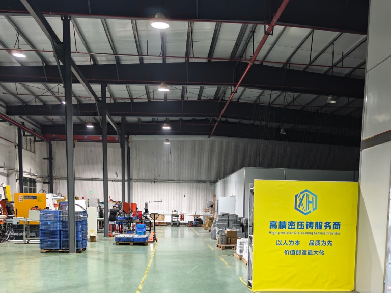
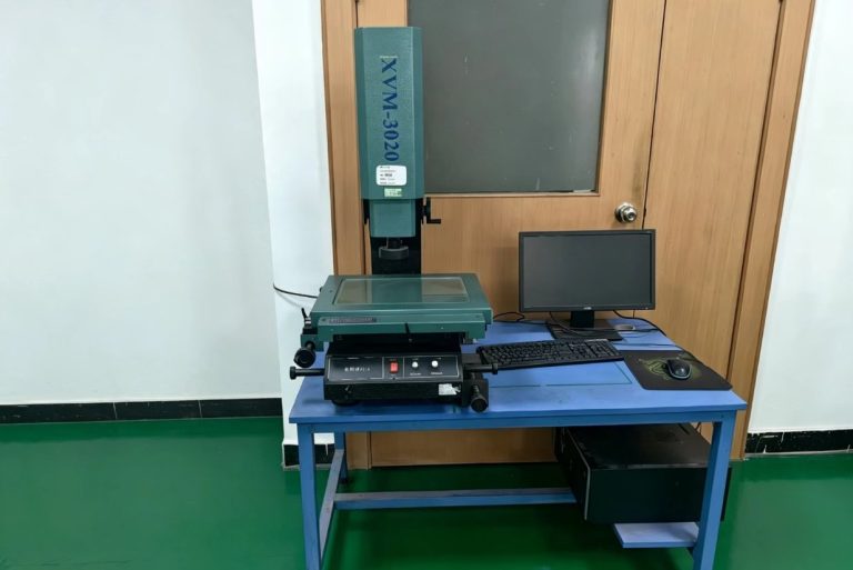
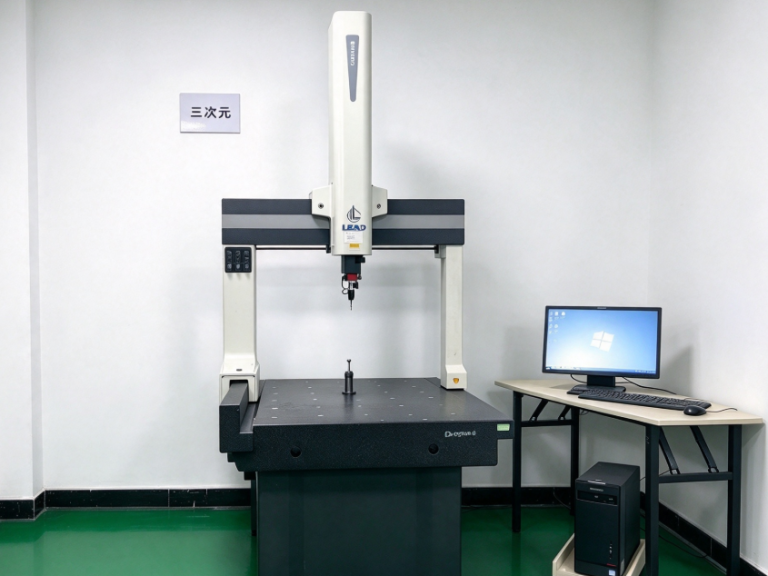
Tolerance capability is half equipment and half die design plus early communication. We run aluminum on TOYO machines and zinc on LK and Shimi machines — seven die casting machines in total, with CMM verification on dimensions. Zinc minimum order is 3,000 shots; samples come 5–7 days after trial, production around 15 days.
If you have a drawing and want to know whether it can be cast and whether the tolerances need adjusting, send it over. We answer with DFM findings, not a guessed price.